The simplicity of Vertical Axis Wind Turbines has major advantages but historically VAWTs have not been as efficient as Horizontal Axis Wind Turbines ( HAWTs). As previously pointed out in the section “ look at the limitations of and how vertical axis wind turbines work,” The design constraints of existing VAWTs limits the potential for scaling up. It was also pointed out that HAWTs are becoming bigger but with a reduction in efficiency.
Improvement of the efficiency of VAWTs has been demonstrated by using pitch control and also by the tweaking of substantial symmetrical aerofoil profiles
Pitch control (via the control of a canard) is an important feature of the new concept previously outlined on this site.
The efficiency of any size VAWT could be improved by using aerofoils of variable geometry.
The deployment of flaps alters the lift and drag coefficients of an aerofoil very significantly. Ailerons are flaps that can be deployed in both directions. The deployment of ailerons, that are almost full length, on VAWT aerofoils is a means of optimising the lift force while in both the windward and leeward sides of a revolution.
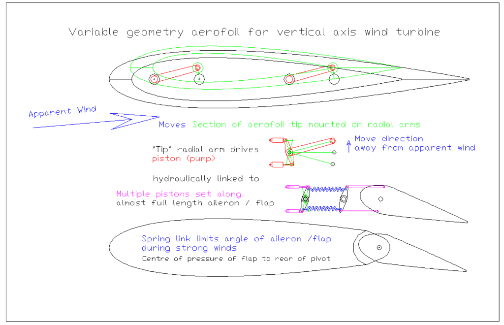
By mounting the tip of an aerofoil on parallel arms of equal length the tip can move away from an apparent wind with no alteration to the angle of attack. The rotation of those arms can then be used to drive the position of the aileron. There are many ways in which that can be accomplished, but for long aerofoils it is envisaged that hydraulics could be advantageous. In the example shown the aerofoil’s chord is tangential to the circle of rotation and the angle of attack of apparent wind will vary but it will always be on one side when the aerofoil is in the windward part of its rotation and on the opposite side while in the leeward part of its rotation. The tip will move dependent only on the direction ( windward or leeward ) of the apparent wind. This drives hydraulic pistons, which act as pumps, The pump pistons being of a larger bore are linked to a number of pistons to move the ailerons. For large aerofoils, which would have large ailerons the force on the ailerons due to stronger winds needs to be limited. A spring link within the system would limit such forces, by limiting the angle of deployment of the ailerons. To ensure that the aileron deflection is limited its centre of pressure must be to the rear of the pivot.
Large aerofoils must be able to feather into wind to reduce the angle of attack during extremely strong winds.
The novel system with pitch control using a canard , previously discussed, incorporates this feature but normally VAWTs with fixed aerofoils do not. ( There are no really large VAWTs yet.) Large aerofoils could be mounted such that they could rotate about an axis forward of their centre of pressure, with the rotation against a preset torque, which would return them to their normal position. For example multiple cams with pressurised followers could apply a returning torque. The bottom of the aerofoil could be connected to such a shaft / cam arrangement.
A lesson from sailing: When the wind is stronger the boat heels over more. Not that it is practical to heel an individual aerofoil, inclining such an aerofoil reduces the angle of attack of the apparent wind on it, reducing the load on it.
How to incline an aerofoil : Split the aerofoil into two sections with a pivot between them, with the pivot parallel to the chords. The frame that supports the pivot ensures the pivot is tangential to the circle of rotation. Each frame could be mounted on a giant flywheel or as in the illustration below onto a float connected to a submerged framework that connects to a generating hub.

Manufacturing the aerofoil in 2 identical parts is the most economical. A tip can be added to each one such that the top one has a bigger area but the bottom one is slightly heavier. In the centre there is torque resistance / return system. For example cable fixed to a drum can be fixed to a weight via a hydraulic damper. When a combination of the difference in area of the tips, the angle of attack ( windward or leeward) and the wind speed causes the torque ( of either direction) to pick up the guided weight, the aerofoil inclines, which reduces the angle of attack. This will only happen when the design limits for normal operation are reached. The torque to increase the inclination depends on the mass difference between the tips and the offset of the tip to the vertical. If the aerofoil is one of variable geometry controlled by a moving tip, a counter balance and arm ( not shown) can be added to prevent G forces or inclination influencing the position of the tip . Note as the inclination approaches the horizontal the angle of attack approaches zero and the lift forces on the tip decrease to zero resulting in no deflection of the aileron with no lift force on the aerofoil. this is equivalent to being fully feathered into wind.
The general principle can be applied to units which have aerofoils sections of different lengths and a lower pivot point, but it may be important to maintain the pivot point at the aerodynamic centre of the sections. It is complicated slightly by the effects of wind shear. But note the effect of shear in strong winds is reduced due to any inclination of the aerofoil.
The illustration shows sealed ballast tanks within “catamaran ” floats. These floats with their support frames for the aerofoils allow them to pivot on a submerged frame. This frame forms a full ring round and is connected to a floating generating hub via spoke / cables. The pivoting of the floats removes any twisting stress that might otherwise be imposed on the “ring” frame but allows for tangential and radial loads. The torque from the radial load on the aerofoil times the height of the pivot is absorbed by additional displacement of one hull and the raising of the other.
The water will rotate with the frame and the Couette flow / fluid flywheel effect are the same as previously outlined.